Basic Functions
- Draw function for all Annotation Styles will be left-click (Desktop)
- To pan around the print while drawing an Annotation, hold down the Space bar and left-click to move the current view
- On touch-screen devices, use a two-finger swipe to pan around the print
- The screen will auto-pan if the Annotation being drawn reaches the edge of the screen (for both desktop and mobile)
- If an Annotation is being moved, the screen will also auto-pan as the Shape, Text Field, etc. being moved reaches the edge of the screen
- When a Text object is created, it will be dropped in the center of the screen
- If the view is zoomed out when the Text object is dropped, the view will be zoomed in closer to the Text object
- When a Shape is being drawn or edited, the size of the nodes will adjust based on how far out the user’s view is zoomed

If the Grid is on while an Annotation Shape is being drawn, the lines of the Shape will snap to the nearest gridlines
-
- The Grid can be turned on/off as needed during editing
Accessing the Annotations Menu
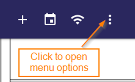
- Click the Menu icon at the top right of the screen
-
Click the Layers option

- Click Annotations to access a list of existing Annotations and the Create New Annotation button

Create a New Annotation
- In the Annotations menu, click the Add (+) icon

- Enter a Name for the new Annotation layer
- Select a Privacy Setting
- Public: All users can view the Annotation, but only the users with the Annotation Editor permission can make edits
- Locked: All users can view the Annotation, but only the creator can make edits
-
- Private: Only the creator of the Annotation can view or edit it

- Private: Only the creator of the Annotation can view or edit it
- Click SAVE to create the Annotation and access the drawing functions in the Annotation Toolbar
- See Annotation Toolbar section for details

- See Annotation Toolbar section for details
- Click CANCEL to exit the creation of the new Annotation and return to View Print mode
The Annotation Toolbar
The table below shows brief descriptions of all the tools/options available when creating or editing an Annotation:
|
TOOL |
DESCRIPTION |
 |
Shapes: choose an object or shape |
|
|
Fill: choose a fill option (No Fill, Translucent, Opaque) |
|
|
Color Selector: choose a color from the palette (the selected color will display in the box) |
 |
Line Style: choose a style for No-Fill Shapes (Solid, Dotted, Dashed, Both) |
|
|
Line Weight: increase or decrease line thickness (1 through 10) |
|
|
Undo: removes recently drawn Shapes/Objects in the order in which they were drawn |
|
|
Redo: re-adds recently removed Shapes/Objects in order in which they were removed |
 |
Snap: Choose from the available options to select how the lines snap when drawing (same functionality as the Measurement Tool) |
 |
More: Clicking this icon expands to show the options below… |
|
|
Measure: can be used to gain square footages |
|
|
Arrow: adds an Arrow at the end of a Polyline Annotation |
|
|
Send to Front: brings the selected Annotation to the top if multiple shapes are layered on top of one another |
|
|
Send to Back: sends the selected Annotation to the back if multiple shapes are layered on top of one another |
 |
Square Footage Total: When an Annotation includes square footage measurements, this tool will auto-calculate the total after saving |
|
|
Clone: a copy/paste function for Shapes, Text, and Objects (see below section on Cloning Annotations for more information) |
|
|
Horizontal Flip: flips the Annotation horizontally across the screen, i.e. across a vertical axis |
|
|
Vertical Flip: flips the Annotation vertically down the screen, i.e. across a horizontal axis |
|
|
Name/Privacy: allows user to modify the layer name and privacy level |
|
|
Delete: deletes the currently selected Annotation, or deletes the entire Annotation Layer if nothing is selected |
|
|
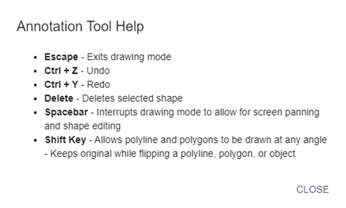
Help: selecting this option will open up a list of available “hot keys” on the keyboard (Desktop Only); see below for the available hot keys |


Drawing New Shapes
- To begin drawing, first select an option from the Shapes menu

- Choose a Fill setting (if applicable)
- No Fill: the Shape will remain an outline (this is the default option)
- Translucent: the interior of the Shape will be shaded with the color selected in the toolbar but the floorplan below will still be visible
- Opaque: the interior of the Shape will be filled with the selected color and the floorplan below will not be visible
- For Polyline and Text Shapes, this setting will default to No Fill and cannot be edited

- Choose a color for the Shape from the Color Palette
- The selected color will be indicated by the small square in the toolbar
- For Shapes with a Fill setting, this will be the color of the entire Shape
- For No Fill Shapes, this will be the color of the object outline

- Choose a Line Style
- For Shapes with a Translucent or Opaque Fill selected, it is not necessary to select line style
- See table below for examples of how each line style will appear


- Choose a Line Weight
- Use the slider to increase the heaviness of the line, or use the text field to manually type in the desired weight (a scale of 1-10, 10 being the heaviest)
- For Shapes with a Translucent or Opaque Fill selected, it is not necessary to select line weight

- If line measurements and/or arrows are needed for this Shape, select the option from the More menu on the Toolbar (see the Annotation Toolbar section)

- When the Measure option is selected, the unit can be changed from the default selection of Feet via the Units of Measurement option in the UNITY menu
- The Arrow option is available for Polylines only and will add an arrow to the end of the line in the direction the line is drawn

- After all desired options have been selected, left-click on the print to begin drawing the Shape, using the cross-hairs as a guide
- When drawing Rectangles or Circles, left-click once on the print and then drag until the desired size is reached, then single left-click to finish

- When drawing Rectangles or Circles, left-click once on the print and then drag until the desired size is reached, then single left-click to finish
- When drawing Polygons or Polylines, left-click to add the first point of the shape and continue to left click at all necessary points/angles until the desired shape is reached, then double left-click to finish

- After completing an object, it will automatically be selected for editing, as indicated by an orange box around the shape (see below section on Editing Annotations)
Adding Text Fields
- To add text to an Annotation, select the Text option from the Shapes menu

- This will open the Text Input field in the Toolbar and drop a default text field on the print, approximately in the middle of the screen, that is automatically selected (orange outline) for editing

- Click in the Text Input field and begin typing to replace the default text

- The Color Palette can be used to change the text color

- Click the Text Size icon to open the slider to adjust the size of the text
- Desired text size can also be typed in as indicated below
- Default text size is 50 on a scale of 1-400, with 400 being the largest

Adding Objects
Objects are custom shapes designed to represent common items used in space planning such as office equipment, furniture, and more.
- Open the Shapes menu to add an Object to an Annotation layer

- The Objects menu is divided into different categories
- Click a Category to view the Objects available in that Category

- Click a Category to view the Objects available in that Category
- Select the desired Object from the list of options

- After an Object has been selected, hover the cursor over the print and left-click to add the Object to the layer

- After the Object is dropped it will automatically be selected for editing
- The selected Object will also remain attached to the cursor until the user hits the Esc key, meaning multiples of the same Object can be added to the Annotation layer without having to select it from the menu each time
 When an Object is in Edit mode, the color or line weight of the Object can be modified the using the same process as with Text and Shapes.
- When an Object is in Edit mode, it can be re-sized by clicking on one of the orange nodes and dragging to the desired size.
- Objects have a “locked aspect” ratio, meaning they can be re-sized but they cannot be stretched out of proportion.

- Objects have a “locked aspect” ratio, meaning they can be re-sized but they cannot be stretched out of proportion.
- Objects can also be rotated when in Edit mode by clicking the handle and dragging to the desired orientation

Edit Existing Annotations
Whether a new Annotation Layer is being created or modifications are being made to an existing Layer, editing Shapes, Text, and Objects that are part of the Annotation Layer will be the same.
- In the Annotations menu, click the Edit Pencil Icon next to a layer to open it for editing

- This will open the Annotation Toolbar at the bottom of the screen
- See Annotation Toolbar section for details on the options available in the Toolbar

- See Annotation Toolbar section for details on the options available in the Toolbar
- To begin editing an Annotation, left-click on the Shape, Text, or Object and hold until the nodes on the object appear
- The Toolbar can then be used to edit Fill Style, Color, Line Style, etc. using the same processes detailed in the “Create an Annotation” process
- Nodes indicate an object is in edit mode, as shown below
- The shape of an existing Annotation can NOT be changed, i.e. a Rectangle cannot be changed to a Circle

- The size of an Annotation can be modified by clicking on a node and dragging the cursor

- An Annotation can be relocated to a different area on the print by left-clicking anywhere within the object or text that is NOT a node and dragging the cursor

- To remove a Shape/Text Field/Object from an Annotation Layer, there are two options:
- The Undo button, which will delete the most recently drawn item first and then previous items with each subsequent click (the Redo button will bring them back, if needed)

- Left-click and hold to select a Shape/Text Field/Object, then click the Delete button in the More section of the Annotation Toolbar OR the Delete button on the computer keyboard to remove the selected item

- The Undo button, which will delete the most recently drawn item first and then previous items with each subsequent click (the Redo button will bring them back, if needed)
-
- IMPORTANT NOTE: If a Shape/Text Field/Object is not selected, clicking the Delete button will open the below message. DO NOT CLICK DELETE UNLESS YOU WISH TO DELETE THE ENTIRE ANNOTATION LAYER!
- If you do not wish to delete the entire Annotation, click CANCEL to return to the Annotation
- To delete the entire Annotation, click DELETE to confirm the removal
- IMPORTANT NOTE: If a Shape/Text Field/Object is not selected, clicking the Delete button will open the below message. DO NOT CLICK DELETE UNLESS YOU WISH TO DELETE THE ENTIRE ANNOTATION LAYER!

Cloning Annotations
Existing Shapes, Text, and Objects can be reproduced on the print with the exact formatting as the original.
- To Clone an existing Shape, Text, or Object, left-click and hold to place the item in Edit mode

- From the Toolbar, open the More menu and click Clone

- An exact reproduction of the selected Shape, Object, or Text will appear on the print next to the original
- The clone will automatically be selected for editing

- The clone will automatically be selected for editing
Saving the Annotation Layer
- To save a new Annotation Layer or any changes to an existing Annotation Layer, click the Save button at the top right of the map view

- To discard the new Annotation Layer or any changes to an existing Annotation Layer, click the (X) icon in the Annotation Toolbar

- To delete an entire Annotation Layer, make sure no objects or text fields are selected (or only the selection will be deleted) then click Delete in the More section of the Annotation Toolbar

- The user will be prompted to confirm or cancel the Delete action

Cloning an Entire Annotation Layer
An entire Annotation Layer can be cloned to a new map or the same map. The clone will be an exact copy of the original, including the name (which can be changed), but any features of the Annotation clone can be modified using the methods explained previously in this article.
- To clone an Annotation layer, open the Annotation menu and click the icon to the far right of the name of the Annotation

- You will be prompted to select the desired location destination for the Clone
- Only locations with F1 MAPS loaded will be available as a destination for the Clone

- Once the desired location is selected, click SAVE to clone the Annotation layer to the selected destination
- Click CANCEL to discard the clone

- After saving, the cloned Annotation will be available on the new floor plan and can be modified as needed
Annotation Touch Support
Users on iPads and other mobile touch-screen devices can edit existing and create new Annotations (provided they have the appropriate permission). On touch-screen devices, the Annotation Tool will operate essentially the same, until it comes to drawing Shapes.
- Draw a Rectangle, Circle, or Rounded Rectangle: tap first corner then tap into the final corner, or drag to final corner and tap to complete
- Draw a Polyline or Polygon: works essentially the same, just tap around the points of the Shape and then double-tap to complete
- On touch-screen devices, use a two-finger swipe to pan around the print